Die Casting Design Guide
Design for die casting comes down to one mental model: molten metal enters a steel die at high pressure, freezes from the walls inward, and the part must then get out of the die. Every rule in this guide — uniform walls, generous draft, ribs over bulk, radii over corners — follows from that model. Understand the model and the rules stop being arbitrary.
This guide covers the decisions that matter most, in the order they usually bite. It will not replace an engineering review — geometry is too specific for that — but it will make your first submitted model dramatically closer to production-ready, which shortens quoting and saves tooling money.
What are the key die casting design rules?
The core die casting design rules: keep walls thin and as uniform as possible (uniformity beats thickness); add draft to every face parallel to the die's opening so the part ejects; radius internal corners to help metal flow; use ribs rather than thick sections for stiffness; and design bosses and features that fill and eject cleanly. Getting them right before steel is cut is far cheaper than fixing a tool. Inox Die Cast reviews your 3D model against these at the DFM stage.
At a glance
- Wall thickness is the master variable — uniformity beats thickness
- Draft, radii and the parting line decide whether the part ejects
- Ribs and bosses that fill, not features that fight the die
- Send the model early — changes are cheapest before steel is cut
Wall Thickness: The Master Variable
Uniformity beats thickness. Metal freezing at different rates in thick and thin sections creates porosity, sink and distortion — so the goal is not 'thick enough' but 'even enough'. Where sections must change, transition gradually rather than stepping abruptly, and expect the review to probe every junction where thick meets thin.
Thinner is usually better, within reason. Thin walls cool faster, cycle faster and save metal on every shot; the limit is set by flow length, alloy and geometry, not by a universal number. Zinc fills thinner sections than aluminum, and walls near the gate can go thinner than walls at the end of the fill path. When a wall must be minimal, tell the review which one — gating can often be arranged to feed it.
Cored-out bulk is the pattern to internalize. Where a solid mass seems structurally necessary, the casting answer is almost always a shell with ribs: same stiffness, less metal, faster cycle, no porosity nest. If your model has any region thicker than roughly twice its neighboring walls, redesign it before the review does.

Draft, Radii and Getting Out of the Die
Draft — the small taper on faces parallel to the die's opening direction — is not optional. Zero-draft faces drag against the die, scar the surface and wear the tool; the fix costs a fraction of a degree at design time. Interior walls need more draft than exterior ones because castings shrink onto cores as they cool. As-cast surfaces that must be truly vertical are better machined after casting.
Radii do double duty: sharp internal corners concentrate stress in the part and in the die, and they impede metal flow. Round everything you can. Where two walls meet, a radius comparable to the wall thickness is a sound starting instinct — the review will tune from there. Parting-line placement deserves a thought at design time too: the die must split somewhere, that split leaves a witness line, and deciding where you can tolerate it beats discovering where the tool designer put it.
Undercuts deserve suspicion. Features that trap the part in the die need slides or lifters, each adding tooling cost, cycle time and maintenance. Many undercuts dissolve under redesign: reorienting a boss, splitting a feature across the parting line, or accepting a machined groove instead of a cast one. Flag every undercut you keep, so the tooling quote prices it knowingly.
Ribs, Bosses and Features That Work
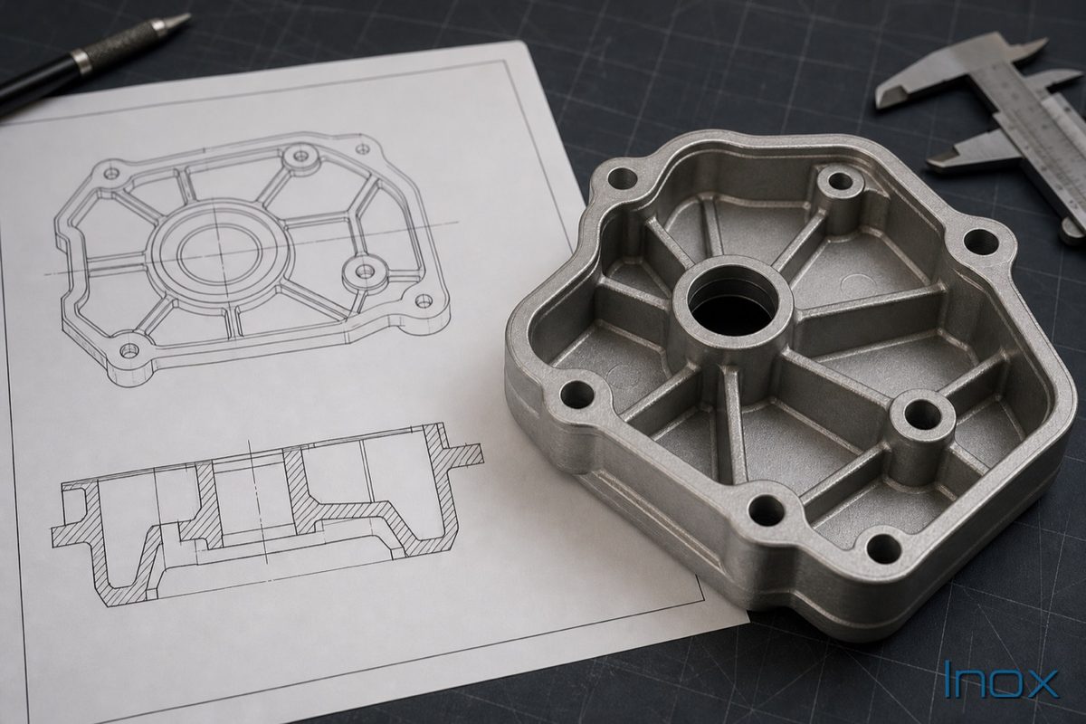
Ribs stiffen without bulk: keep them thinner than the wall they support to avoid sink marks on the opposite face, give them draft, and run them along load paths. Bosses — the towers that receive screws — want supporting ribs or gussets rather than surrounding bulk, and their holes are best cast as pilots then drilled or tapped where fastener engagement is critical. Cast-in text and logos work well when raised rather than recessed and placed on surfaces the die can reach. Every feature should answer one question: does the die form it easily, or is machining the honest route? And remember the ejector pins: the part must be pushed out of the die by something, those pins leave small marks, and flat hidden surfaces are the cheapest real estate to give them.
Representative application illustration — not a record of a specific customer program.
The Pre-Submission DFM Checklist
Run your model down this list before sending it. Each 'no' is a conversation the review will start:
| Check | Passing looks like |
|---|---|
| Wall uniformity | No section thicker than ~2× its neighbors; gradual transitions |
| Draft present | All faces along die-opening direction tapered; more on interior walls |
| Corners rounded | Internal radii on the order of wall thickness; no knife edges |
| Undercuts justified | Each one flagged, priced, or redesigned away |
| Bulk cored out | Solid regions replaced by shells and ribs |
| Bosses supported | Gussets or ribs, not surrounding mass; pilot holes for threads |
| Machining separated | Tight-tolerance and sealing faces marked for machining, not hoped from the die |
| Cosmetic zones marked | Visible faces identified so gates and ejectors land elsewhere |
| Alloy direction stated | Aluminum or zinc chosen, or the question explicitly open |
| Volume honest | Annual quantity stated — it drives every tooling decision |
Frequently Asked Questions
What wall thickness should I start with?
Start from function and let uniformity govern: pick the thinnest wall that carries your load or thermal duty, then keep everything else within about a factor of two of it. Absolute numbers depend on alloy, flow length and geometry — zinc runs thinner than aluminum — and the engineering review will confirm the specific walls your model can carry.
How much draft do I need?
More than zero on every face parallel to the die's motion, with interior faces needing more than exterior ones because the part shrinks onto cores. Treat published degree tables as starting points, not guarantees: depth of the feature, surface finish requirements and alloy all shift the answer, which the tooling review settles per face.
Can die casting produce threads?
External threads can sometimes be cast; internal threads are almost always better drilled and tapped, or handled by threaded inserts. Cast pilot holes get thread engagement where it matters at lower total cost than the tooling gymnastics of die-formed internal threads. Mark the fasteners that carry real load so the review treats them accordingly.
Should I design for aluminum or zinc first?
Decide before detailing thin features — zinc forgives thin, intricate geometry that aluminum resents, while aluminum carries heat and structural mass zinc cannot. If the material question is open, say so in the RFQ: it is easier to steer a model toward the right metal early than to translate a finished design across the boundary.
Will you review our design before we commit to tooling?
Always — that review is how every program here starts, and it is where wall, draft, undercut and gating questions get settled against your actual geometry. Send the model with critical features marked and the volume stated; the feedback comes back specific, from the team that would build the tool.
Where to Go Next
Design review
Run the Checklist, Then Send the Model
A model that passes this page's checklist quotes faster and tools cheaper. Send it with the volume and the critical features marked — the review picks up exactly where the guide leaves off.
Last reviewed August 2026 · Inox Die Cast, Dongguan